Every hydraulic system ever designed is affected by a simple “four letter word” – HEAT
Where there is a “Pressure Drop”, there is heat.

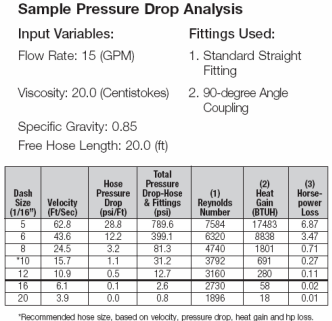
Anytime fluid flows from an area of high pressure to an area of lower pressure without producing mechanical work (Pressure Drop), heat is generated. Friction, type and temperature of fluid, length and size of hose assembly, type of couplings and adapters, and flow rate are all examples of things that can influence the amount of pressure drop. Conducting a Pressure Drop Analysis will determine the amount of pressure drop in the system. One simple solution is to upsize the components and reduce the bends in the plumbing. If radical bends are unavoidable, increasing the size of the hoses and fittings will increase the flow capacity dramatically. Example:10 GPM through #10 SAE hydraulic hose flows at a velocity of 10 fps, while the same 10 GPM flows at 7.5 fps through #12 SAE hose. This method will decrease the heat load by a 25% decrease in flow restriction, resulting in an increase of efficiency of the hydraulic system!
Increasing heat dissipation is another technique used to cool an overheating hydraulic system. In order to achieve stable oil temperature, a hydraulic system’s capacity to dissipate heat must EXCEED its inherent heat load. Heating of the hydraulic fluid in operation is caused by inefficiencies, resulting in losses of input power (PL), which are converted into heat. The size of the heat exchanger required to cool away operational heat load is equal to the total power losses of the hydraulic system, which can be expressed as: 
In practice, the total power loss of a hydraulic system cannot be calculated due to the number of unknown variables. Heat exchangers are used to remove the excess heat in a hydraulic system. The implementation of heat exchangers has many variables that need to be taken into account. Rules of thumb when sizing a heat exchanger is as follows:
- Simple circuit with minimal valves: 25%
- Simple circuit with cylinders: 25%
- Simple circuit with fluid motors: 31%
- Hydrostatic transmissions: 35 – 40%
- Servo based systems: 60 – 75%
- Low-pressure fluid transfer: 15%
If the system is a simple circuit with fluid motors and has an electrical motor input horsepower of 30hp: 30hp x 0.31 = 9.3hp
The tank needs to dissipate at least 9.3hp or the system will overheat. Keep in mind that if your system pressure is above 1000psi and the tank is sized for 3 times or less pump output, a heat exchanger will be required.

